Plotting with the VIC Driver in AutoCAD 2000+
Screening Patterns & Line Weights:
Both AutoCAD and Repro Desk have the ability to control the line weights, pen colors, and screening patterns. In AutoCAD this is accomplished with the plot style tables. In Repro Desk it is the pen set. However, there are some differences in how these are implemented in each. The biggest difference involves how screening patterns are defined.
In Repro Desk, each pen may be assigned a specific screening pattern, which can be used to shade certain elements of the drawing. This screening pattern is a specific pattern of dots and independent of the pen’s RGB value.
AutoCAD allows a screening value to be placed on each of the pens. However, rather than using a screen pattern, the screening value actually adjusts the RGB value of the pen by the specified percentage. For example, a red pen that was screened to 50% would become a pink pen on white paper.
When plotting to a black and white plotter, these differences become more pronounced. In Repro Desk, a line drawn with a 50% pen pattern will print lighter than a line drawn with a solid pattern. With AutoCAD, a 50% screened line will print the same as a 100% screened line since both are solid colors with differing RGB values.
Most of the black and white plotters offer a color mode that will convert the RGB values of the pens into the equivalent grayscale value. In this mode, the customer can draw the section that he wants to appear lighter on paper in a lighter color, which will be converted to a lighter shade of gray when it is printed. In Repro Desk this same effect is accomplished via the “Map Pen Colors to Shaded Half-Tone” setting in the pen set properties.
However, a significant problem with this is that all of the pens become shaded grayscale, when the desired effect may have been that only a certain area should be lighter. Yellow and cyan are particularly susceptible to this problem. For example, the yellow lines of a wall segment may have a screening value of 100%, but when sent to a black and white printer they would still print out Very light gray instead of black, contrary to the intentions of the author.
The good news is that with proper planning and usage, the VIC driver can be used to generate either of the desired results.
VIC.PC3 vs. VIC24.PC3
When using the VIC driver from inside AutoCAD, there are two options, the VIC3.PC3 and the VIC24.PC3. Which one you use depends on your desired output.
If you want to plot using line weight and screening patterns controlled by Repro Desk, you should use the VIC.PC3 file. You’ll also need to configure a Plot Style Table that correctly sets the pen numbers in the VIC file to match the color numbers used in the drawing.
If you want to plot using the line weights and screens defined in an AutoCAD Plot Style Table use the VIC24.PC3. Below is a more detailed description of the attributes & requirements for each:
In order to make sure you get a VIC file that can be used with a Repro Desk Pen set you must correctly configure the Plot Style Table in AutoCAD. The BuzzVic.ctb file is setup for this purpose and will provide transparent pen settings to be utilized in Repro desk. Each AutoCAD pen color will be plotted to the specific color of that pen, not “use entity color.” The virtual pen number should match the color number. The Color depth should be set to 255 virtual pens.
This setting can be found in the properties of the Vic.pc3 file (device and document
settings/Graphics/vector graphics/color depth) The Repro Desk Pen Set should have all of the Properties in the “allow drawing to manipulate” set to off. The pen numbers used in the VIC file will match the colors used in drawing. With the Repro desk pen set the desired weights and screen settings can be set for each pen.
VIC24.PC3:
This version embeds the pen numbers, line weights, and pen colors into the resulting VIC file. In the Repro desk pen set the first 5 options of “allow drawing to manipulate” should be set to on, since it will allow the drawing (the VIC file) to control the line weights & pen colors. You will have to turn on the 6th setting (map colors to a shaded half tone) if you want the pen colors to map to an equivalent grayscale value. To achieve correct line weights, in the properties of the Vic24.pc3 file, you will need to have the color depth set to 16 million pens (device and document settings/Graphics/vector graphics/color depth)
When using the VIC24.PC3, you will not be able to reliably know what pen numbers are used, as AutoCAD may use the same pen number but change its color halfway through the file to draw other geometry. For this reason, you can not reliably apply Repro Desk pen patterns to a file created in this way.
It is important to understand that this is the recommended way to configure the Pen Style table. Other ways will work but results become unpredictable. It is also important to understand that this is for the purposes of mono or black and white plotting. Settings required for color plotting are substantially different. This spec is based on a Color Style Table. A Named Style table can be created using similar settings.
1) Open the AutoCAD Plot Style Manager.
2) Select <Add-A-Plot Style Table Wizard>.
3) In the window click <Next>.
4) In the next screen select <Start from Scratch>.
5) Click <Next>.
6) Select <Color_Dependent Plot Style Table>.
7) In the next screen enter a file name.
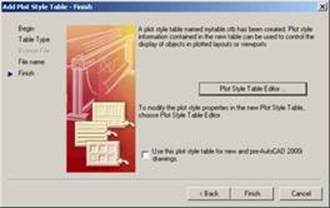
8) Click <Next> this screen will appear:
9) Click the Plot Style Table Editor button and the editor will appear.
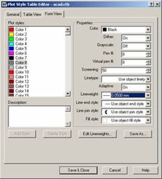
 10) The column on the left is the list of colors that are
used to set the properties of the entities used in AutoCAD drawings. The
properties box on the right allows the user
10) The column on the left is the list of colors that are
used to set the properties of the entities used in AutoCAD drawings. The
properties box on the right allows the user
to specify the settings to be used when plotting the AutoCAD
entities.
11) You can select all of the
Color Numbers by using the shift key or pick and choose by using the Ctrl key.
For this purposes start by selecting all of the colors in the Plot Styles
list.
12) Set the properties for these as follows:
Color - Black
Dither – Off
Grayscale – Off
Pen # - no longer used
Virtual Pen # - 7
Screening – 100
Linetype - Use Object Linetype
Adaptive – Off
Select the End style and Join style of your choice
typically both are set to Round.
This will produce Plot Files with all pens mapped to black.
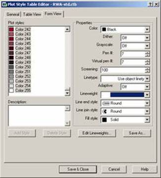
To embed screen values select the entity color
you want to screen in the Plot Styles Column.
Change the following settings for that color:
Dither on.
Virtual pen # should be set to the plot style color #.
The pen number is no longer used.
Screening – the screen percent you want
the line to be for example 50 for 50% or 25 for 25%
It is important to understand some things about the Buzzsaw.com
Vic driver in order to
properly set the Lineweight Values. Vic files are always created at 400 DPI.
Therefore all lines that can be created in the Vic file are in increments of
1/400th
of an inch or in decimal .0025”.
Any other values used for lineweights will be rounded and possibly create undesirable results. For example a lineweight of .0075” would produce a line that is 3 400 DPI pixels, a lineweight of .00875” would be rounded and could produce either a 3 or 4 pixel width line.
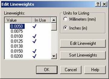
Before you can set the line weights for the color numbers the lineweights need to be edited. Click the Edit Lineweights button. The following screen will appear:
Change the Units for Listing to Inches (In)
Right Click on the Value to edit and select Edit Lineweights. Change the value to a multiple of .0025.
The following schedule may help you determine the values you need to enter.
|
Number of Pixels |
Decimal Inches |
Technical Pen Sizes |
|
1 |
0.0025 |
|
|
2 |
0.0050 |
6x0 |
|
3 |
0.0075 |
4x0 |
|
4 |
0.0100 |
3x0 |
|
5 |
0.0125 |
00 |
|
6 |
0.0150 |
0 |
|
8 |
0.0200 |
1 |
|
10 |
0.0250 |
2 |
|
11 |
0.0275 |
2.5 |
|
13 |
0.0325 |
3 |
|
16 |
0.0400 |
3.5 |
|
19 |
0.0475 |
4 |
|
22 |
0.0550 |
6 |
When you have completed editing the lineweights select the Color Number in the Plot Style column and then select the desired line width in the Lineweight combo box. Repeat this for all colors you use in your drawings.
Once you have completed these settings, save and close the Plot Style Table Editor. It will be saved into the default location selected for Plot Styles in the options dialog you can also set this as your default Plot Style. Drawings created before the creation of this Plot Style Table will be set to use a different table select this table before plotting these drawings.